
What Is a Hydraulic Power Pack? Complete Guide
A hydraulic power pack integrates a motor, pump, reservoir, valves, filters, cooling, and often a manifold to supply controlled hydraulic pressure and flow. This guide covers design, specifications, selection, and maintenance.
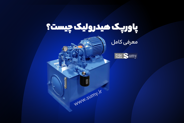
What Is a Hydraulic Power Pack? Complete Guide, Components, Technical Specifications, and Expert Selection Advice
What is a hydraulic power pack? A hydraulic power pack is often described as the heart of a hydraulic system because it supplies the energy required to move and operate different types of equipment. In heavy industry, road-construction machinery, production lines, and automation systems, hydraulic power packs are integral components.
This article takes a detailed look at hydraulic power-pack components, technical details, advantages, and important considerations for selection and maintenance.
What Is a Hydraulic Power Pack?
A power pack is an integrated unit consisting of a motor, hydraulic pump, reservoir, and control valves. Its purpose is to supply the pressure and flow required by a hydraulic system. The unit is installed independently of the main machine and, once connected to the hydraulic circuit, delivers pressurized oil into the circuit.
Main Components of a Hydraulic Power Pack
To understand how the system works, its main components should be considered individually:
1. Motor
The motor is the primary source of mechanical energy in the power pack. Two common types are used:
-
Electric Motor:Suitable for industrial environments with three-phase or single-phase electrical power. It is relatively quiet, efficient, and easy to maintain.
-
Diesel or Gasoline Engine:Suitable for remote, mobile, or off-grid applications. It can provide high power but is noisier and requires fuel and regular servicing.
Technical Note:Motor power commonly ranges from about 0.75 kW to 30 kW in the applications described by the source and should be selected according to system working pressure and required flow.
2. Hydraulic Pump
The pump draws oil from the reservoir and supplies it to the circuit under pressure. Depending on the application, one of the following types may be used:
-
Gear Pump:Simple and economical; the source describes applications up to about 150 bar.
-
Vane Pump:Typically smoother and quieter than a gear pump, with pressures stated at approximately 180–200 bar.
-
Piston Pump:Offers high precision and efficiency and is used for higher pressures, stated here as approximately 250 to 700 bar, particularly in demanding applications.
Important Characteristic:The pump should be able to supply the fixed or variable flow required by the system with suitable accuracy.
Hydraulic pumps available from Fidar Nadin Sumy
3. Oil Reservoir
The reservoir stores hydraulic oil and performs several functions:
-
Stores enough oil to supply the system.
-
Provides time and space for contaminant particles to settle.
-
Helps cool the oil through heat exchange with the surroundings.
-
Allows entrained air and gases to separate from the oil.
Reservoir Capacity:The source recommends a reservoir capacity commonly around two to four times the pump's per-minute flow rate.
4. Control Valves
This section controls system pressure, flow, direction, and operating sequence and may include the following valves:
-
Pressure-Relief Valve:Prevents excessive pressure and protects the system from damage.
-
Directional-Control Valve:Determines the path of oil flow through the circuit.
-
Flow-Control Valve:Controls the speed of a hydraulic cylinder or motor.
-
Solenoid Valve:Can be controlled remotely by a PLC or other controller.
5. Filters
Filters remove contamination from the oil. Fine suspended particles can cause severe wear in pumps and valves.
-
Suction Filter:Installed before oil enters the pump.
-
Return-Line Filter:Helps prevent contaminants from returning to the reservoir.
-
Pressure-Line Filter:Used in precise or contamination-sensitive systems.
Note:Filters should be equipped with a clogging indicator where appropriate.
6. Cooling System
Systems operating at high power and pressure can generate substantial heat. A cooling system helps protect the oil and hydraulic components from excessive temperature.
-
Air Cooler:Uses a fan and oil radiator or heat exchanger.
-
Water Cooler:Uses water flowing through a heat exchanger to reduce oil temperature.
Important Technical Specifications for a Hydraulic Power Pack
When designing or selecting a power pack, several technical parameters should be considered:
1.Working Pressure
The pressure at which the system is designed to operate effectively. Depending on the application, the source gives values ranging from about 100 to 700 bar.
Example:A working pressure around 250 bar is common in some heavy-cylinder applications.
2.Flow Rate
The amount of oil transferred per unit time, commonly expressed in liters per minute. This parameter directly affects the operating speed of a hydraulic cylinder or motor.
Approximate Formula:Cylinder speed (m/s) = flow rate / cylinder cross-sectional area
3.Motor Power
Motor power can be estimated from the following relationship:
P (kW) = (Q × p) / (600 × η)
where Q is flow rate in L/min, p is pressure in bar, and η is total efficiency.
4. Reservoir Volume
For continuously operating systems, the source recommends a reservoir volume approximately two to four times the pump's per-minute flow to provide adequate cooling and settling time.
5.Oil Type
Selecting hydraulic oil with an appropriate standard viscosity grade, such as ISO VG 46 or ISO VG 68, is important. Lower-viscosity oil is generally used at lower temperatures and higher-viscosity oil at higher temperatures, subject to equipment-manufacturer requirements.
Advantages of Using a Hydraulic Power Pack
-
High Force from a Compact Package:Especially useful where machine space is limited.
-
Precise Speed and Pressure Control:Achieved using suitable valves and control equipment.
-
Continuous Operation Under Demanding Conditions:Suitable for industrial environments, high temperatures, or variable loads when correctly designed.
-
Fast, Independent Installation:Can be installed as a self-contained unit without replacing a central power source.
-
Customization:Each power pack can be designed around the requirements of a specific project.
What Is a Hydraulic Manifold and Why Is It Important in a Power Pack?
In a professionally designed hydraulic system, coordinated and precise control of oil flow is essential for safe and correct equipment operation. This important function is handled by the hydraulic manifold, a component that may appear simple externally but plays a critical role in system behavior.
A manifold is a metal block containing precisely machined internal passages for hydraulic fluid. Different hydraulic valves, such as pressure-, directional-, and flow-control valves, are installed on or in the manifold. It therefore acts as a central connection point for hydraulic control functions.
Where Is the Manifold Located in a Power Pack?
In a hydraulic power unit or power pack, the manifold is normally installed close to the pump and oil reservoir and is connected directly or indirectly to the pump outlet. With control valves mounted on the manifold, flow can be distributed and controlled to actuators such as cylinders and hydraulic motors in an integrated assembly. This layout reduces the space occupied by the system and can simplify maintenance and repair.
Why Is a Manifold Important?
The advantages of a manifold extend beyond compact design. Important reasons for using one include:
-
Reduced piping and unnecessary fittingswhich can reduce the number of potential leakage points.
-
Faster and more precise control of hydraulic-fluid flow.
-
Easier design of complex hydraulic circuits.
-
Ability to customize the system by adding or removing valves.
Manifold Design Options
Manifolds are generally available in two broad configurations:
-
Block-Type Manifolds:Common in compact industrial applications.
-
Modular Manifolds:Suitable for systems that may require frequent expansion or modification.
The appropriate design is selected according to project requirements and system complexity.
Important Points for Power-Pack Design, Operation, and Maintenance
- Change hydraulic oil at intervals of approximately 1,000 to 2,000 operating hours where this matches the equipment maintenance plan.
- Inspect and replace filters according to the maintenance schedule.
- Keep operating temperature below about 60°C where specified for the system.
- Do not ignore small leaks; they can develop into serious failures.
- Check the pressure gauge and temperature indicator regularly to detect excessive pressure or temperature.
- Carry out a technical inspection of the pump and motor at least annually where appropriate for the duty cycle.
Conclusion
A hydraulic power pack is a compact, reliable, and effective power-transmission unit used in many industrial systems, road-construction machines, mining equipment, and production lines. Accurate design, correct component selection, and proper maintenance are essential for stable and reliable operation. Engineers and industrial operators therefore benefit from understanding the unit's internal components and key technical parameters.
If you plan to purchase or design a power pack, first consider the required duty, working pressure, pump type, and environmental conditions, and consult a hydraulic specialist where necessary.