
Solenoid Valves
A solenoid valve is an electromechanical valve that uses an electrical coil and plunger to start, stop, or control fluid flow. This guide covers direct-acting, pilot-operated, AC/DC, glandless, and hydraulic solenoid valves.
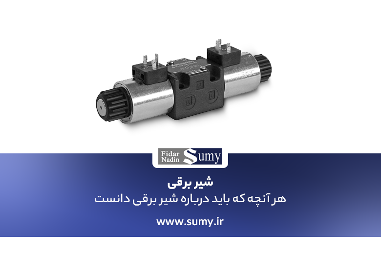
A hydraulic solenoid valve is a valve operated by electrical force to start, stop, or regulate fluid flow in a hydraulic system. A hydraulic solenoid valve consists of a valve body
connected to an electrical coil mechanism, or solenoid, capable of opening, closing, or controlling fluid flow. The control system produces this change according to the command it receives.
A solenoid valve combines two main functional units:
- A solenoid, or electromagnet, with its core.
2. A valve body containing one or more ports or orifices.
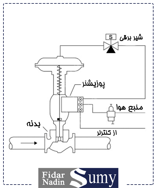
The solenoid valve is normally open, allowing the positioner output to enter the diaphragm case. If electrical power is lost, the solenoid valve closes the port to the valve positioner and vents pressure from the control-valve diaphragm case.
Where solenoid valves are installed in controlled-air supplies to pneumatic valves in order to lock diaphragm pressure, the source states that an electrical failure arrangement should include a time delay and manual reset so that brief power interruptions do not cause unintended operation.
Introduction to Actuators
Solenoid Valve
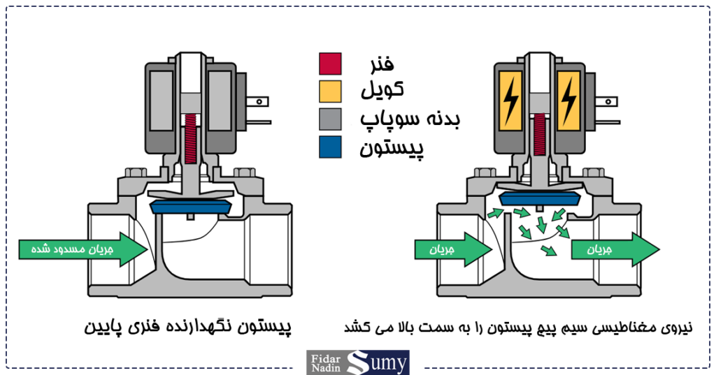
A solenoid valve is an electromechanical valve that opens or closes when electrical power is applied or removed. Solenoid valves are used with both pneumatic and hydraulic actuators. The control panel shown in the figure above uses a single solenoid valve.
Where a higher safety level is required, such as an emergency shutdown function, two or three solenoid valves may be used on the control panel. The figure below illustrates solenoid-valve operation. The right-hand view shows the condition in which electrical power is applied to the solenoid valve.
The coil is energized and creates a magnetic field around the plunger, shown in blue in the source illustration. The magnetic force pulls the plunger upward and opens the valve, as shown in the figure.
When electrical power is removed, the magnetic field collapses, the plunger moves downward, and the valve closes.
Control Valves
Solenoid Valve
A solenoid valve is essentially a valve operated by an internal actuator consisting of an electrical coil and a plunger. An electrical signal opens or closes the valve, and the mechanism returns to its initial position, usually by spring force, when the signal is removed.
Solenoid valves are manufactured as normally open or normally closed, referring to the valve position when the solenoid is not energized.
DC or AC Solenoid Valve
The source states that DC solenoids are often preferred because they do not have the same initial inrush-current peak as AC coils, reducing the risk of overheating or coil damage, especially when the valve is cycled frequently or the spool becomes accidentally obstructed.
However, where faster response is required or relay-based electrical controls are used, AC solenoids may be preferred. The source gives response times of about 8 to 15 microseconds for AC solenoids and about 30 to 40 microseconds for DC solenoids.
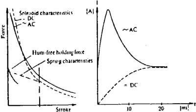
There are notable operating differences between valves supplied with DC and AC coils. According to the source, DC coils have a slower response and are limited to lower pressures, while AC coils respond more quickly and can initially handle higher pressure.
See the figure above. This faster response can permit more rapid cycling when required. Electrical losses, however, increase with AC frequency; for example, the source states that losses for a 60 Hz AC solenoid are greater than for the same coil on a 50 Hz supply.
Effect of the Return Spring
With a two-way normally closed valve, both spring force and inlet-fluid pressure act to close the valve. The return spring can therefore be relatively weak and, in some designs, can be omitted entirely. The latter arrangement requires the valve to be installed so that the solenoid is vertical,
with gravity, together with fluid pressure, providing the return action as shown in the figure below.
With a two-way normally open valve, the spring, assisted by fluid pressure, holds the valve open. The solenoid force must be sufficient to overcome both the spring force and inlet pressure in order to close the valve.
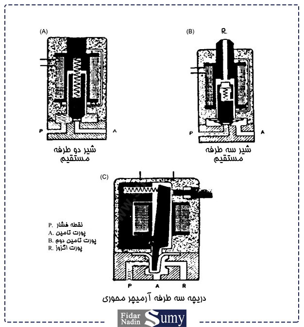
Three-way valves require upper and lower springs. The lower spring presses the valve onto its seat, which is opened by inlet pressure. The upper spring acts in the direction shown in positions B and C of the figure above. The source summarizes the required combination of spring strengths as follows:
Valve Type — Upper Spring — Lower Spring
Three-way normally closed — strong — weak
Three-way normally open — weak — strong
Mixing valve — medium — medium
Diverting valve — strong — weak
Pilot-Operated Valves
Direct solenoid operation is generally limited to smaller valve sizes. Larger solenoids capable of directly operating larger valves consume more electrical power and produce considerable heat.
A pilot-operated valve is often a more attractive solution in such cases. A small solenoid operates a pilot valve, which in turn admits inlet pressure to the appropriate part of the valve to open the main valve.
The pilot supply may be internal, using line pressure from the valve itself, or external, using a separate pilot source.
For a pilot-operated valve to work correctly, some differential pressure must exist across the main valve. With this differential available, the valve can control higher line pressures with relatively low electrical input. The pressure rating of the main valve is coordinated with that of the pilot valve
because both are exposed to the same line pressure. Pilot-operated valves generally have slower response times than direct-acting solenoid valves, although many designs allow this response to be adjusted.
Everything You Need to Know AboutHydraulic Pumps!
Semi-Balanced Valve
Another general category of solenoid valve is described in the source as a semi-balanced valve. It is a double-seated valve with two plugs mounted on a common stem. The lower plug is slightly smaller than the upper plug. Line pressure acts beneath the lower plug
and above the upper plug, creating a differential force that helps hold the valve on its seats, assisted by a spring where required. The solenoid therefore only has to overcome the force produced by the pressure imbalance, plus spring force if present, to open the valve.
Electrically Operated Hydraulic Valves
A preferred design arrangement for an electrically operated hydraulic valve is to use solenoid force for the "push" action and spring action for the return or "pull" movement. The solenoid must be powerful enough to overcome inertia and friction as well as spring and hydraulic forces.
The hydraulic forces can vary considerably and may not be fully predictable, so a generous design margin is required in the rating of the solenoid and springs.
A solenoid may be of a "dry" or "wet" type. In general, a wet solenoid can be smaller for the same duty because static and dynamic friction are lower. Wet designs also have the advantage that all moving parts are enclosed and lubricated
and the dynamic seal between the solenoid and valve body can be eliminated. These are also described as glandless valve designs.
Direct-acting solenoid valves are generally limited to flow rates of about 45 L/min in the range described by the source, including nominal valve sizes around 1/8 in and 1/4 in. Many can be switched directly by solid-state control systems. Typical coil ratings cited in the source are 24 V DC and approximately 20 to 65 W, depending on the system.
Glandless Solenoid Valve
By arranging the solenoid armature to operate inside a sealed tube surrounded by the electrical coil, sealing glands can be eliminated. This simplifies construction and removes a potential leakage point. The principle is widely applied to smaller valves.
A typical arrangement is shown in the figure below. Glandless valves can be installed in various positions and can withstand substantial shock loads. The response time is described as very short:
the source states about 5 microseconds on AC and 10–15 microseconds on DC, with cycling rates of several hundred cycles per minute said to be possible.
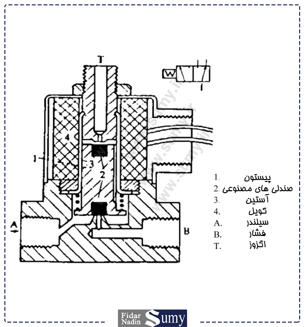
This principle is widely applied to smaller valves. A typical type is shown in Figure 16.36 in the source. Glandless valves can be installed in different positions and can withstand substantial shock loading. Their response time is described as very short:
about 5 microseconds on AC and 10–15 microseconds on DC, with cycling rates of several hundred cycles per minute said to be possible.
Solenoid-Valve Characteristics
When solenoid valves are used in process lines, the valve body should comply with the applicable instrument-piping specification. The source states that standard manufacturer's bronze construction is normally suitable for air service.
Valve-body connection sizes should be 1/8 in, 1/4 in, and 3/8 in, or as specified on the relevant data sheet.
Solenoid coils should be molded and encapsulated and should use continuous-duty Class E or Class F insulation at the specified rated voltage and frequency.
The solenoid itself may operate from a DC or AC supply. Standard electrical ratings given by the source include 24 V AC or DC and 110 V AC at 50 Hz, or other values specified on the data sheet.
Unless otherwise stated on the data sheet, the solenoid coil should operate the valve with voltage variations of approximately ±10%.
A variety of valve-body materials is available. Valve-seat materials should be selected to suit the service. The source lists materials such as Buna-N, stainless-steel discs, Viton, PTFE, and others; selection should follow the requirements stated on the data sheet.
External parts of the solenoid-valve construction that come into contact with the process fluid should be stainless steel, according to the source.
Direct-acting three-way and four-way packless solenoid valves that require no minimum operating pressure may be mounted on control valves. Both miniature and standard solenoid valves are available with general-purpose enclosures that protect against indirect splash and dust
or with explosion-resistant and weatherproof/watertight enclosures. The required enclosure should be specified by the user on the relevant data sheet.
The enclosure should be suitable for the area classification specified on the data sheet.